Modern data centers demand storage architectures that are not only highly available and secure but also capable of scaling seamlessly without causing operational disruptions. NetApp Clustered Data ONTAP (commonly referred to as Cluster-Mode or c-mode) represents a paradigm shift from traditional dual-controller storage architectures to a unified, scale-out storage platform. Originally evolved from NetApp’s acquisition of Spinnaker Networks in 2003 and commercialized through Data ONTAP GX in 2006, Cluster-Mode has become the cornerstone of NetApp’s ONTAP 9 operating system.
This comprehensive guide dives deep into the netapp cluster mode architecture, explaining its physical and logical components, network infrastructure, storage virtualization layer, and how it compares to legacy architectures like 7-Mode. Whether you are a system administrator, a storage engineer, or an IT architect, this guide will provide the technical depth required to master NetApp’s scale-out storage solutions.
What is NetApp Cluster Mode Architecture?
NetApp Cluster-Mode (c-mode) is a scale-out storage architecture that groups multiple independent storage controllers (nodes) into a single, cohesive cluster. Unlike traditional storage systems that limit you to a single pair of controllers, a NetApp cluster can scale up to 24 nodes for file protocols (NFS, SMB/CIFS) and up to 12 nodes for block protocols (FC, iSCSI).
From an administrative and client perspective, the entire cluster behaves as a single, virtualized storage pool with a unified namespace. This means clients can access their data from any node in the cluster, regardless of where the physical disks hosting that data are located. This abstraction is made possible by combining physical hardware, dedicated high-speed networking, and logical virtualization layers.
Key Physical Components of NetApp Clustered ONTAP
To understand how Cluster-Mode functions, we must first break down its physical building blocks. The hardware architecture is designed around redundant, modular components that eliminate any single point of failure (SPOF). For a detailed breakdown of the physical controller layout, see our guide on NetApp Cluster Mode Hardware Architecture.
1. Controller Nodes
A node is a single storage server running the ONTAP operating system. Each node consists of CPU, memory, NVRAM (for write logging), network interface cards (NICs), Host Bus Adapters (HBAs), and dedicated storage connections. Nodes are responsible for processing read/write requests, managing RAID groups, executing storage efficiency features, and handling system administration tasks.
2. Disk Shelves and Media
Disk shelves house the physical storage media, which can include Solid State Drives (SSDs), Non-Volatile Memory Express (NVMe) drives, or traditional Hard Disk Drives (HDDs). These shelves are connected to the controller nodes using SAS (Serial Attached SCSI) or PCIe/NVMe-oF cables in a redundant loop configuration, ensuring multiple paths to the data.
3. High Availability (HA) Pairs
In a NetApp cluster, nodes are always deployed in High Availability (HA) pairs. An HA pair consists of two controllers that are physically cabled to the same set of disk shelves. They are also linked via an HA interconnect (often a dedicated PCIe link or high-speed Ethernet connection). Under normal operations, each controller owns its specific set of disks and serves data independently. However, if one controller fails, its HA partner instantly takes over its storage ownership and continues serving data with minimal to no disruption to the clients.
The Logical Storage Layer: Storage Virtual Machines (SVMs)
One of the most powerful features of the netapp cluster mode architecture is the absolute separation of physical hardware from logical data access. This virtualization is achieved through Storage Virtual Machines (SVMs), formerly known as Vservers.
An SVM is a secure, isolated logical storage server that runs within the cluster. It contains its own administrative security, logical network interfaces (LIFs), and dedicated storage volumes. A single physical cluster can host hundreds of SVMs, making it an ideal architecture for multi-tenant environments. For example, you can easily configure file-sharing services by learning how to create a CIFS share in SVM Netapp Cluster Mode. Similarly, for block storage setup, you can follow our tutorial on how to configure iSCSI in SVM NetApp Cluster Mode.
Logical Components within an SVM
To understand how data flows through an SVM, we must look at its internal logical structure:
- Aggregates: A physical collection of disks grouped together using NetApp RAID-DP (Double Parity) or RAID-TEC (Triple Erasure Coding). Aggregates provide the physical storage capacity.
- Flexible Volumes (FlexVols): Logical storage containers carved out of aggregates. FlexVols are where the actual files, directories, or LUNs reside. They can be dynamically resized, moved, or cloned.
- Logical Interfaces (LIFs): Virtual IP addresses or World Wide Names (WWNs) associated with physical network ports. LIFs are assigned to SVMs and serve as the network access points for client data traffic.
Because LIFs and FlexVols are logical, they are not permanently tied to any physical node. If a controller node becomes overloaded or requires maintenance, ONTAP can non-disruptively migrate a LIF to another physical port and move a FlexVol (using the volume move command) to a different aggregate on another node, all while clients are actively reading and writing data.
Network Architecture of Clustered ONTAP
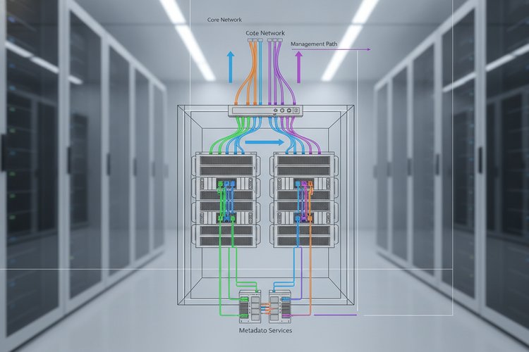
A robust network infrastructure is essential for the scale-out capabilities of NetApp Cluster-Mode. According to the NetApp network architecture overview, this separation ensures that client data access, internal cluster coordination, and administrative actions do not interfere with one another. The architecture utilizes three distinct, isolated networks to handle different types of traffic:
1. The Cluster Interconnect Network
This is a dedicated, private, ultra-low-latency Ethernet network that connects all nodes in the cluster. It is used exclusively for internal node-to-node communication, cluster heartbeats, database replication, and data routing. If a client connects to Node 1 but needs to access data physically located on disks owned by Node 2, the data is routed across the Cluster Interconnect. NetApp utilizes redundant, high-speed switches (such as Cisco Nexus or Broadcom BES-53248 switches) running at speeds of 10GbE, 25GbE, 40GbE, or 100GbE to prevent bottlenecks.
2. The Data Network
The Data Network connects the storage controllers to the client infrastructure (servers, hypervisors, and workstations). It supports a wide array of storage protocols, allowing unified storage access over Ethernet and Fibre Channel networks:
- File Protocols: NFS (Network File System) and SMB/CIFS (Server Message Block) for file-level sharing.
- Block Protocols: iSCSI (Internet Small Computer Systems Interface), Fibre Channel (FC), and NVMe over Fibre Channel (FC-NVMe) for block-level storage.
3. The Management Network
This network is dedicated to administrative traffic. It allows storage administrators to connect to the cluster via the System Manager GUI, Command Line Interface (CLI), or REST APIs. The management network is divided into:
- Cluster Management: A single logical interface (Cluster Management LIF) that provides access to the entire cluster regardless of which node is currently hosting it.
- Node Management: Dedicated physical ports on each controller node for individual node administration and troubleshooting.
- Service Processor (SP) / BMC: Out-of-band management interfaces that allow administrators to access the hardware console even if the ONTAP operating system is offline.
Deep Dive: How Data Flows Through the Cluster
To fully grasp the power of the netapp cluster mode architecture, it is helpful to look at how read and write requests are handled across the system. Because of the abstraction layers, data access can be either symmetric or asymmetric.
The Write Path and NVRAM Replication
When a client issues a write request to a Logical Interface (LIF):
- The request arrives at the physical port hosting the LIF on Node A.
- Node A receives the write and logs it to its local NVRAM (Non-Volatile RAM) to ensure durability.
- Simultaneously, Node A replicates this write log across the HA Interconnect to the NVRAM of its HA partner (Node B).
- Once the partner node acknowledges the NVRAM write, Node A sends a write acknowledgment back to the client. This entire process takes microseconds.
- Later, during a process called a “consistency point” (CP), ONTAP flushes the writes from NVRAM to the physical disk shelves using WAFL (Write Anywhere File Layout).
Indirect Data Access via the Cluster Interconnect
What happens if a client connects to a LIF on Node A, but the target volume resides on Node C (which is in a different HA pair)? This is where the Cluster Interconnect shines:
- Node A receives the request and recognizes that the target volume is owned by Node C.
- Node A encapsulates the request and forwards it over the high-speed Cluster Interconnect network to Node C.
- Node C processes the read/write request on its physical disks and sends the result back to Node A via the interconnect.
- Node A delivers the data back to the client.
This process is highly optimized and occurs with negligible latency, ensuring that the unified namespace remains incredibly fast and responsive.
Clustered ONTAP vs. Traditional 7-Mode
For years, NetApp storage systems operated on Data ONTAP “7-Mode” (or 7G/8-Mode). While 7-Mode was highly reliable, it had structural limitations that prompted the development of Cluster-Mode. The table below outlines the core differences between these two architectures:
| Architectural Feature | Data ONTAP 7-Mode | Clustered Data ONTAP (c-mode) |
|---|---|---|
| Scaling Limit | Maximum of 2 controllers (1 HA pair) | Up to 24 nodes (12 HA pairs) in a single cluster |
| Namespace | Isolated namespaces per controller | Single unified global namespace across all nodes |
| Storage Virtualization | None (controllers map directly to clients) | Storage Virtual Machines (SVMs) abstract physical hardware |
| Data Migration | Disruptive or complex offline migrations | Non-disruptive volume moves (vol move) and LIF migration |
| Hardware Upgrades | Requires planned downtime (controller swap) | Rolling tech refreshes with zero client downtime |
Key Benefits of NetApp Cluster Mode Architecture
By shifting from 7-Mode to Cluster-Mode, enterprises gain significant operational and financial benefits:
1. Non-Disruptive Operations (NDO)
In traditional environments, software updates, hardware replacements, and capacity rebalancing require scheduled maintenance windows, leading to business downtime. In a NetApp cluster, these tasks are performed non-disruptively. Data is dynamically moved to other nodes while a controller is updated, rebooted, or replaced, maintaining continuous client access.
2. Seamless Scale-Out and Scale-Up
As storage demands grow, administrators can scale up by adding larger disks and shelves to existing nodes, or scale out by adding new controller nodes to the cluster. New nodes can be mixed and matched (e.g., combining high-performance All-Flash FAS nodes with hybrid FAS nodes), allowing organizations to tier their storage dynamically within a single cluster.
3. Built-In Multi-Tenancy
With SVMs, organizations can easily partition a single physical cluster for different departments, customers, or workloads. Each SVM has its own security, network routing, and storage policies, preventing data leakage and ensuring performance isolation.
4. Advanced RAID Protection (RAID-DP and RAID-TEC)
NetApp ONTAP utilizes specialized RAID configurations designed to protect against multiple simultaneous disk failures without sacrificing performance. To learn how RAID works alongside other optimization techniques, check out the storage efficiency features of NetApp Cluster Mode.
- RAID-DP (Double Parity): Protects against the simultaneous loss of two drives within a RAID group. It is the default RAID type and offers superior protection compared to RAID 6.
- RAID-TEC (Triple Erasure Coding): Protects against up to three simultaneous drive failures. This is highly recommended for ultra-large capacity HDD and SSD aggregates where rebuild times are longer.
Conclusion: The Future-Proof Storage Foundation
The netapp cluster mode architecture has revolutionized how modern enterprise storage is deployed, managed, and scaled. By virtualizing physical controllers and storage media into logical Storage Virtual Machines, and linking them via a dedicated Cluster Interconnect network, Clustered ONTAP delivers unmatched high availability, multi-tenancy, and scale-out capabilities.
Understanding these physical and logical mechanisms is essential for any technical professional working with NetApp systems. As organizations transition to hybrid cloud environments, the architectural foundation of ONTAP 9 ensures that data can move fluidly between on-premises data centers and public clouds, providing a consistent, reliable, and high-performance data fabric.